Blog Image

The next eshine telescope

Design ideas and tests for a new generation of automatic earthshine telescope

What did we learn from the first try?

Centering

Automation Posted on Mon, May 20, 2013 14:45:56

The pointing of the telescope was not perfect. We set the pointing by calibrating the mount on a target field of stars the position of which we found using image-analysis software (see astrometry.net). The centre of field was then added, by hand, to a setup menu, and the telescope would centre well for a while. After a meridian flip, or after a few days, the centring was not so good any more.

We tested polar alignment by the drift method, but results were not clear. We are thus unsure why the pointing of the mount would deteriorate.

GOTO telescopes have calibration modes where a sequence of observations at different parts of the sky are made so that a pointing model can be calculated and used. We could not do this – we did one pointing and updated the model based on that – we needed a way to access the ‘build a pointing model’ system by software. Even to do this automatically.

We had the basic ingredients of a system to take pictures of the Moon and centre accordingly, but it was not functioning robustly.

The dream solution would be something like this: the system is lost and does not know where it points – so it takes a picture of the sky and gets an astrometric solution – then it gets more – if one solution does not work it gets more pictures, at random
above-horizon, places – and keeps going until a solution is found. Then it goes about its work. Sigh.


Focus

Automation Posted on Mon, May 20, 2013 14:37:14

We needed to focus the system now and then – but it turned out that this was when the wrong filter had been selected. In view of this, there may never have been a focus problem – as long as the filter was correctly selected the system would proceed to set focus to that filter.

There was never an automatic ‘set the focus’ operation, but perhaps this was not needed? It would have been required if we had gotten the NDs up and running as a known laboratory-tested focus point for these may not have been at hand, and then it would have been necessary to find it by hand and setting a fixed value.


Groundwinds dome

Housing Posted on Mon, May 20, 2013 14:32:58

We were housed in a fine house at MLO, using the Groundwinds old dome.

Extra hardware had to be installed to move the dome correctly. The dome would ‘stick’ on the track now and then and screech its way round. It was not fast – 2 minutes for a full circuit.

A never-fixed software problem had to do with addressing the position –
after some operations the dome ‘had to’ perform a full circuit before
it was happy to go to where we wanted it to go.

Most problems were our fault – it took a long time to generate software that pointed the dome opening where the telescope was pointing. This is standard stuff in commercial ‘observatory software’.


Equatorial mount

Pointing Posted on Mon, May 20, 2013 14:26:45

The equatorial mount we got was a 1200 LX-200 GOTO mount from AstroPhysics. Once we stopped sending the wrong codes to it it worked fine. Like all LX-200s (all?) there is ‘wild slewing’ if commands arrive in the wrong order. We had a timeout that was too short and a code was sent before the last one was done – messaging during slewing is a seriously bad idea for LX-200 mounts.

Once working as it should, we saw it was a rugged and accurate mount – pointed where we wanted it to point within a few arc minutes. Only problem – as with all equatorials – is the need for meridian flip. This was never automated, so we were stuck with the default which is that slewing across the meridian is not impossible, and highly catastrophic. So we put in limit switches and stopped the scope before the meridian – did the MF – and re-centred.

Alt-AZ would not have a MF but images would rotate. Can image de-rotators work well? And automatically? And without adding extra scattered light?

Is there a “don’t message while slewing”‘ issue with alt-az LX-200 GOTO mounts? I think there is.

Need to review how “indiserver” and “ascom” setups work for various types of mounts!


The CCD was fine, or was it?

CCD Posted on Mon, May 20, 2013 12:47:43

The Andor iXon-897 BV CCD camera had some properties we need to review

The RON was low (2 ADU/pixel in practise, 1ADU/pixel in the brochure …)

The bias pattern was strong, as it is on thinned CCDs. The level of the bias was temperature dependent and as the camera was cooled in a thermostat loop the mean strength of the bias pattern had to be adjusted for this. We did this by using only bias frames taken just before and after the science images and scaling a ‘superbias’ field. If the superbias was representative of the actual pattern we are probably doing well _ but this in itself should be tested. We certainly have the data! All shout: Student Project!

Linearity: We have data that suggest that the CCD was not ‘99% linear’ as all CCD brochures promise. As the evidence depends on the shutter being linear with exposure time we have to revisit this.

We had ‘dark bands‘ matching the width of the Moon, in the readout direction. While we may have compensated for this by doing ‘profile fitting’ also in the row direction of the image we would like to know what was going on, and choose a future CCD accordingly.

CMOS: they are available in 16-bits (Andor) and colour (in DSLRs: expensive!). Now, what was the benefit of using CMOS instead of CCD? Need to compare linearity and readout speed.

Some aspects of the expensive Andor were of no practical use for us: ability to have EM – that caused the bias average bias to flicker by +/-1 counts (not pixels – the average!). Faster readout modes were available, but never used – they cut into dynamic range or gave more noise. An internal shutter was a possible option but was not chosen – so we had to rely on the dodgy external one! A possible coating and enhancement of the blue-sensitivity was not chosen – choosing it would have left the red-sensitivity unaltered, so why not get it?

Cooling with water was possible but never used as it would be just so much more plumbing to worry about.


Secondary optics and the halo

Optics Posted on Mon, May 20, 2013 12:35:44

We seem to have evidence (in SKE experiments) that the ‘halo’ is generated in the system after the prime focus – this includes 2 secondary lenses, a Lyot stop, various hardware near the optical beam (SKE, colour FW, ND FW). Just where does the scattering occur? If it is in the two lenses then why do they seem to add disproportionally much, compared to the primary objective? At the time of design there was talk about ‘super-polished lenses’ and its use in the primary, but I think the tests in Lund showed there was little effect. That supports the idea that little scattering occurs in the primary – so why in the secondaries? Were inferior lenses used there? Would super-polished lenses help there?

There seems to be good arguments for using secondary optics: they provide a collimated beam in which instruments and devices can be placed with only effects on intensity (no shadows) in the final image. But if the secondary lenses cause all the scattering, perhaps we should do without them?

The items in the collimated beam include:
1) Lyot stop – required to remove scattered light – but from what? first secondary lens? or from Objective? or SKE in prime focus?
2) ND and colour filters – get rid of these: use a colour CCD and never use ND filters. We never used them as they depended on the SKE working. Reconsider their need.

More questions:

Can lab experiments, or Zeemax-type raytracing be used to understand scattering in the secondary optics? Or by the various hardware in and near the collimated beam?

The CCD was angled at one point – but was it later realigned to let the ghosts coincide with the image? Are the ghosts providing the ‘halo’?


What we don’t want

Starting up Posted on Mon, May 20, 2013 11:40:42

While it may be hard to build what we want, it is fairly easy to say what we do not want:

We do not want bright light from the Moon to reach the secondary optics – thus a means to avoid that will have to be found. We ought to discuss both external and internal occulters. The internal one was tried and failed – can a better system be invented, based on the same ‘knife-edge-in-prime-focus idea? Could external occulters work? The shadow cast needs to be sharp – it must be far away from the main objective – how do we get it in line with the telescope? How do we change the angle? Should look at digitally addressable LCD arrays of image modulators.

Could non-mechanical SKEs be invented? How about an LCD screen in prime focus with an addressable array of pixels? We place the required shape on the screen so that the BS is coverfed?

Electro-mechanics gave us problems: the SKE broke, the filter wheels stuck, the shutter stuck, it took a long time to get the dome working correctly; the mount had its ‘wild slews’. Some of these problems were of software origin (mount and dome problems in particular, perhaps SKE too, filter wheels and shutter probably not) – but the software was complex in order to make complex hardware move – think simpler mechanics, or design them out of the system, and the software will be simpler. We started by thinking about a dome-free system – revisit that idea.

Why use filter wheels? This was driven by a science idea – perhaps doing wide-band photometry is not useful for science goals? Perhaps it is – but movable filter wheels were a source of trouble – try to use several single-filter cameras and beam-splitters; or one camera with a colour CCD. Look into designing a CCD chip with the filters we want. Any UBVRI CCDs out there?

The Uniblitz shutter failed at times – why have a mechanical shutter? Well, because the camera read-out time was long compared to typical shutter times, so ‘dragging’ occurred if the mechanical shutter was not working. Can we have longer exposure times – or a CCD that reads out faster? Longer exposure times could be obtained if the f-number of the system was larger – but that means a physically longer system. We decided against folding mirrors – but was this a thought-out step? Perhaps the slight dependence on polarization could be designed out somehow? ND filters could also be used – but probably should be fixed or in a foolproof filter wheel. With ND filters, longer exposure times can be had – but then more internal reflections and scatter is added to the mix. Putting an object in the pupil acts to cut down on the image intensity without leaving a ‘shadow’: perhaps a simple device could be placed in the collimated beam, instead of filters – an object would not cause reflections like glass surfaces do. DMA (digital mirror arrays) should be looked into.

The shutter did not work well, but was very expensive. Canon DSLR shutters cost about 20 $ – and seem reliable. All shutters have a limited lifetime – we should think out a way to have easily exchangeable shutters.

Design for less cables. The main cable is an anaconda 20 meters long, thick as a leg. Try to design so that wireless communication (think bluetooth) can be used.

The mount was an equatorial mount – so meridian flips gave us hell. Why not use alt-az mounts? Image rotation can be handled with image rotation devices, or in software. Software solution requires work on “conservative image manipulation” (interpolation is required, but is not conservative unless steps are taken).

Added later: but look here:
http://iloapp.thejll.com/blog/earthshine?Home&post=369

Automation software was written from scratch. Is there no commercial software available that could have worked? Then issues of bugs etc would be in other peoples hands – people with a commercial interest in selling products that worked well to a large audience.

Site choice: Hawaii was extremely good for us – but cost money each year and the distance, despite Ben’s good work, made fixing problems difficult. Let us deploy very close to home for the testing and run-in period, next time!

Above all we do not want systems that are assumed to work! By this I mean we do not want systems that are given a command and after that – without checking – it is assumed that all went well. We want a system that checks, and iterates until a goal is met. So feedback loops – “polling” is the phrase! – perhaps using image processing; position sensors using bar code readers or image analysis from webcams on and in the system, or NFC readers,or in-device compasses and accelerometers.

The design and build was in the hands of relatively few people last time – perhaps we should consider ‘crowd-sourcing’ the design effort? Great way to get lots of ideas (some good, some bad), but above all feedback and interactive discussions. An interested team of ATMs would change the mix!


The Beginning

Starting up Posted on Mon, May 20, 2013 11:06:16

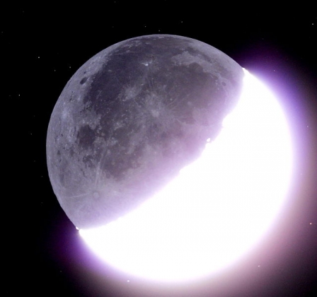
Following extensive experience with the first earthshine telescope on Hawaii, we now try to synthesize what we learned, in order to create a better, cheaper, and more reliable telescope. This blog is like the one at earthshine.thejll.com, so entries can be put into categories, comments can be made and so on.

More to follow!

If you want to join in, please write to me at pth at dmi.dk and ask for an invitation.

Peter Thejll