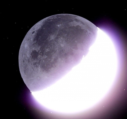
When danish ESA astronaut Andreas Mogensen goes to the ISS in August 2023, he will be performing science experiments for a number of groups. We are one of the groups and have suggested that images of the New Moon be obtained in order to evaluate how much scattered light is avoided when imaging the Moon from above the atmosphere.
Comparing to images taken at the same time through the atmosphere will constitute the Earth-leg of this experiment, conducted by astronomers and interested people with a camera. Communication about this possibility will be conducted through the dmi.dk site and on social media platforms.
Public images posted along with the hashtags #newmoonsnap and #huginn will be collected and evaluated. With ESA it is hoped to make the experiment international.
Images of the New Moon from the ISS
Optics Posted on Sat, May 20, 2023 10:38:40- Comments(0) https://nextelescope.thejll.com/?p=75
- Share
DAVIS neuromorphic camera
CCD, Optics Posted on Fri, July 22, 2022 15:51:03There is a type of camera where the sensor reacts to changes, not to ‘an exposure signal’. The DAVIS 346 Neuromorphic camera is one such.
Data-sheet: https://inivation.com/wp-content/uploads/2019/08/DAVIS346.pdf
Note the apparent high dynamic range of 120dB – like a 100-image stack from MLO?
Wiki: https://en.wikipedia.org/wiki/Event_camera
How can we use an ‘event-based camera’? Can the camera also be triggered from outside?
- Comments(0) https://nextelescope.thejll.com/?p=50
- Share
Effect of broad filters
Optics Posted on Wed, October 29, 2014 13:13:51Using modelling of the Sun-Earth-Moon system it is possible to show that there will be an airmass-dependency in the derived terrestrial albedo. This is due to extinction being colour-dependent and the presence of spectral slopes. The BS is more red than the DS so extinction will relatively influence the DS more than the BS. In monochromatic light the DS and BS would be affected identically by extinction. As our method depends on modelling the DS/BS flux ratio we must either model that colour dependency in the extinction, or correct for the effect with traditional Langley plots of -2.5 log10 (Albedo) vs airmass.
The challenge in modelling the effect is to make avilable wavelength dependent lunar albedo maps and apply them appropriately for the DS and BS individually. LRO maps are wavelength dependent, but correctly representing the colour of the DS and BS seems a bit on the difficult side since we are at the very least dealing with a variable-colour DS.
With narrow filters the problem is less.
This implies that a better future system ought to be based on narrow filters – or on spectroscopy?
It also seems to imply that there will be a signal from terrestrial albedo in the slopes of albedo against airmass. So, when all data are fitted, look for an Albedo vs slope-of-Albedo-vs-airmass relationship.
- Comments(0) https://nextelescope.thejll.com/?p=7
- Share
Non-mechanical filter system
Optics Posted on Sat, October 25, 2014 09:02:43It appears possible to have a variable filter that has no moving parts. It is done with liquid crystals and commands over an rs232 cable:
http://www.dfisica.ubi.pt/~hgil/fotometria/cri/varispec2.pdf
The specs show that you can have a selectable filter from the blue into the NIR – but not in one device. The stability of the ability to dial up a specific filter needs to be investigated. Papers have used this device, such as this one.
The transmittance is low compared to glass, but with a moon that bright, who cares!!!
Scattered light in the filter could be an issue.
Highly sensitive to polarisation — one could make that a feature?
Filter stability would be the other issue — would they change transmission characteristics on long term (year) time scales?
Chris comments:
the transmittance is low compared to glass, but with a
moon that bright, who cares!!!
scattered light in the filter could be an issue.
highly sensitive to polarisation I see — one could make
that a feature?
filter stability would be the other issue — would they
change transmission characteristics on long term (year) time scales?
infrared and optical handled differently, so two would be
needed — could lead to calibration issues…
- Comments(0) https://nextelescope.thejll.com/?p=8
- Share
New KE and optics
Optics Posted on Sat, April 26, 2014 17:41:09Many of the complexities and problems with the present SKE could be avoided by replacing it with a fixed KE. The orientation problem is solved by making the KE in the form of a plate with a sharp-edged hole in – behind some part of the edge of that hole the Moon could always be parked so that just the DS peeked out.
The present size of the Moon on the CCD is a bit too big for this to work. We need to understand which part of the system to rebuild in order to get the Moon to be smaller (perhaps 50% smaller) on the same CCD – or perhaps to get a bigger CCD. The present system is ‘short’ which means that the edges of the field and the centre have problems being in focus at the same time, so a larger CCD would have worse problems (but the worst affected areas would be behind the mask!)
- Comments(0) https://nextelescope.thejll.com/?p=9
- Share
SKE alternatives
Optics Posted on Sun, November 10, 2013 12:16:52It is probably necessary to have that SKE – it leaves a remnant halo, but the intensity of this is very much lower than the halo you get with our co-add technique. Our SKE never worked and I wonder how a potential future one could be constructed?
One alternative could be these ‘Digital Mirror Devices (DMDs)’ which are essentially a adressable semiconductor matrix of little mirrors. The whole things is like a CCD in size but each element can be tipped to one side or the other, thus deflecting light. If one of those devices sat in the prime focus of an objective we could first take an image of the Moon, find the pixels that needed their light deflected, and then address those only and send their light off to one side, thus obtaining a sort of dynamic SKE. Mechanical SKEs still have to be positioned, which I think caused the death of our system – too many motors with dodgy systems for measuring the turning angle, timeouts that never got their timeout and so on.
A DMD array could be fixed in place and operated with software only. Apparently DMDs are evolving fast and in 2014 some kits for experimenting, by Texas Instruments, will come out. The Kits are supposedly some hundreds of dollars.
http://www.ti.com/tool/dlpd4x00kit
They need to be driven by something, and here is a driver board (for $210):
We need to get one of these – with some small pot of money to be raised by sale of stuff from the MLO system (when we decide to do that) – or a small proposal.
Such a DMD undoubtedly has its own PSF and that needs to be tested.
The DMDs have a ‘fill factor’ of about 90% – so an issue is what happens to the remaining 10%. Is it diffusely scattered or is it cast in another direction? Apparently there are three states to a DMD pixel – left, off and right, where the left and right states position the light at +/- 14 degrees. The Off state is to be understood.
- Comments(0) https://nextelescope.thejll.com/?p=11
- Share
New telescope designs
Optics Posted on Tue, October 29, 2013 14:31:08An interesting paper

describes a new design for an earthshine telescope. They describe the essential instrument.
It seems to me that:
1) they only have 2 lenses (although both are doublets – we have one doublet and two singlets)
2) Their masks (like our SKE) sits outside the telescope. At least, that makes it easier to fix when it breaks.
3) Their telescope is a Cassegrain system – so lots of optics there…
Hmm. We should try to understand this design in case we want to try fresh approaches. Perhaps it is an option for a FW-less CMOS-based system?
It seems their ‘instrument’ sits on a conventional telescope – so many many optical surfaces in total…
- Comments(0) https://nextelescope.thejll.com/?p=13
- Share
Secondary optics and the halo
Optics Posted on Mon, May 20, 2013 12:35:44We seem to have evidence (in SKE experiments) that the ‘halo’ is generated in the system after the prime focus – this includes 2 secondary lenses, a Lyot stop, various hardware near the optical beam (SKE, colour FW, ND FW). Just where does the scattering occur? If it is in the two lenses then why do they seem to add disproportionally much, compared to the primary objective? At the time of design there was talk about ‘super-polished lenses’ and its use in the primary, but I think the tests in Lund showed there was little effect. That supports the idea that little scattering occurs in the primary – so why in the secondaries? Were inferior lenses used there? Would super-polished lenses help there?
There seems to be good arguments for using secondary optics: they provide a collimated beam in which instruments and devices can be placed with only effects on intensity (no shadows) in the final image. But if the secondary lenses cause all the scattering, perhaps we should do without them?
The items in the collimated beam include:
1) Lyot stop – required to remove scattered light – but from what? first secondary lens? or from Objective? or SKE in prime focus?
2) ND and colour filters – get rid of these: use a colour CCD and never use ND filters. We never used them as they depended on the SKE working. Reconsider their need.
More questions:
Can lab experiments, or Zeemax-type raytracing be used to understand scattering in the secondary optics? Or by the various hardware in and near the collimated beam?
The CCD was angled at one point – but was it later realigned to let the ghosts coincide with the image? Are the ghosts providing the ‘halo’?
- Comments(0) https://nextelescope.thejll.com/?p=37
- Share
