Here is a code in python that operates the EMCCD camera from Andor: http://code.google.com/p/pyandor/
You will also need a crucial .so file from the Andor SDK for Linux …
What did we learn from the first try?
Here is a code in python that operates the EMCCD camera from Andor: http://code.google.com/p/pyandor/
You will also need a crucial .so file from the Andor SDK for Linux …
For a very light, DSLR-based system, this is a thought:
http://iankingimaging.com/search.php?q=skytracker
How would the mount swing back for start of observations?
It is controllable from various planetarium software packages.
How would it point fine enough?
With a large enough field it would not matter – provided the necessary detail on the DS was observable – perhaps worth a study of the tradeoffs between field size, pixel size and SNR?
In this entry we found some puzzling results. Ignore them! The variance had been screwed up by incorrect procedures on my part. As Hans pointed out, you have to use the method where two images with same exposure (and they must be of an evenly lit surface) are subtracted – the difference has twice the variance of each of the images. This method cancels various common features in the images – blemishes in the flat target as well as uneven response in the chip, and dust on the chip.
Taking a series of twin exposures from very dark to very bright of a white sheet of paper, and extracting a nice square from this, calculating its mean and variance as per above, we get the following result: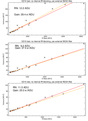
In each panel statistics for R G or B are shown. The readout noise RN is basically the intercept. The Gain is 1./(the slope) of the regression. Two sets of images had to be taken and it would seem the illumination was not even, hence the scatter. Nonlinearities set in for R G and B at various levels – the extent of the x-axis shows the data that are not obviously past the linearity point. So, despite the camera being advertised as 12-bit it has almost 13 bits. Sticking to the 12 seems a good idea – it is all that B can handle, for instance.
We used x3f_extract from proxel.se to extract the R G and B fields from the compressed format X3F files.
This paper by Hytti gets nearly the same as we have above – at least for the G band:

The X3F format images thatthe SIGMA SD10 camera produces are some form of compressed RAW format. It can be dumped out as decoded TIFF files using the
x3f_extract software from the toolkit available at
http://www.proxel.se/x3f.html
I have taken a set of test images of a test card with the internal IR filter removed from the camera, and a Wratten 25A red filter on the lens (and a standard UV-blocking filter). I exposed from a normal setting and with longer and longer exposure times until the images were evidently saturated in all colours, judging from the little histogram on the back of the camera.
After conversion to 16-bit TIFF and reformatting to FITS the mages were inspected and the histograms plotted. As exposure times increased the high edge of the histogram wandered up until it hit some sort of barrier near 10000 counts. This must be the actual saturation level of the camera. It is advertised as 12-bit but that would imply a ḿaximum count near 4096. So it seems we have maybe one bit more than 12 -> 13.
This is a plot of mean value vs standard deviation of a selected square on the test card. There is a linear relationship between S.D: and the mean value … I thought it was mean value and variance … but it breaks down at high mean values.
Added later: Ignore the plot. Look here instead: link
Papers from astrophotography articles that mention the Foven sensor in the SD10 camera:
This paper reminds us of a few things, namely that the camera (like all? CMOS and consumer-grade CCDs) has internal mechanisms for performing dark-subtraction – you do not get to do this by yourself. Exposure time is limited to 2min.
Note also these abstracts found in the ADS:
http://adsabs.harvard.edu/abs/2008AAS…212.2404B
http://adsabs.harvard.edu/abs/2013OptLT..48….1M
This paper may be of general interest:
I have performed some tests of color-separation on the Sigma SD10. The internal IR-blocking filter was present.
I imaged a red, green and blue surface with the camera as is; with the camera and a Wratten25A red filter; and with the camera and a 720nm long-pass IR filter.
Plotting a line across the three coloured surfaces (red at left, green in middle and blue at right), and separating the R G and B fields in the image file, we get:
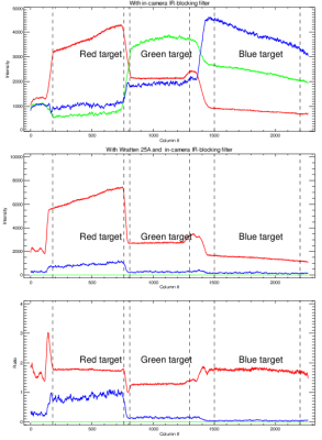
We see
Top panel. No external filters, only internal IR-blocking filter. As
expected, the Red target is bright in the R-band of the image, Green in
the G band, and Blue in the B band.
Middle panel. Now the red Wratten 25A filter is on – i.e. it passes mainly
red light, up to about 560nm, or so. The R band is brightest on the Red target (good); the Green target is supressed strongly everywhere; the Blue band is brightest on the red surface.
Bottom panel. The ratios of panel 1 and 2. Note that exposure times were
not necessarily the same. In the R-band Red and Blue targets seem to have
fared similarly, but the Green target was suppressed by the W25A filter.
In the B-band the Red target was least suppressed by the W25A filter.
In the G band we see strong suppression by the W25A filter for all targets.
Summary: W25A really kills the Greens, but Blues seem to make it through
a bit. Strange that.
The long-pass 720nm filter performs similarly.
The tendency for the G band to ‘drop out’ is seen especially in images of point sources – streaks occur as if the presence of a point source is especially bad for the system. bad news for stellar photometry? We shall see.
A Canon DSLR camera has an IR-blocking filter that has to be removed before the camera allows us to obtain data similar to the B,V, VE1, VE2 we wish to have. It is evidently complex to remove the IR filter form a Canon body – lots of small screws, unbending of glued bits and fragile parts everywhere.
An alternative is the Sigma SD10 camera with the Foveon sensor. The removal of the IR filter from a Sigma SD10 is trivial – one finger can pop the filter out in a second. The SD10 costs about 180 UKP (body only) while the SD15 costs 590 UKP.
We could do away with some of our woes if we used a DSLR CMOS camera instead of the current system. There are several benefits, and a few drawbacks:
PROs: With a DSLR camera we would get RGB colours at the same time, at the same sky conditions, and at the same focus setting. Alignment issues would go away. Shutter precision issues would go away.
With the modifications described in this paper
we would even get the NDVI index which is what we wanted to get by using VE1 and VE2 filters.
CONs:
a) The shutter would be at the focal plane, instead of in the pupil. This could mean that fast exposures were not possible – insertion of a fixed ND filter woudl extend exposure times.
b) With CMOS chips at best being 14 bit (16 bit exist but cost a lot) we could probably not use the ‘direct imaging mode with BS and DS in same frame’.
c) Dark Frame issues appear murky for CMOS cameras. And what about cooling to get stability?
Neutral issues – i.e. same problem as before: We would still need an SKE to block the BS.
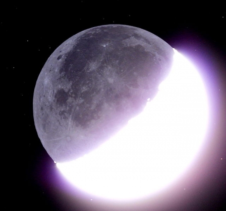
Suggestions:
1) Use an unmodified DSLR to check what the halo structure around the Moon – or Jupiter – looks like in R G and B. If these are the same – which is not the case with Johnson B V and not at all with VE2 – then we might be on to a system to get ‘same-halo images’ with known subtractive benefits! We could then go on and modify a DSLR camera and get the NDVI Index and see if halo issues are reduced.
